Wednesday, Januar 17, 2007
|
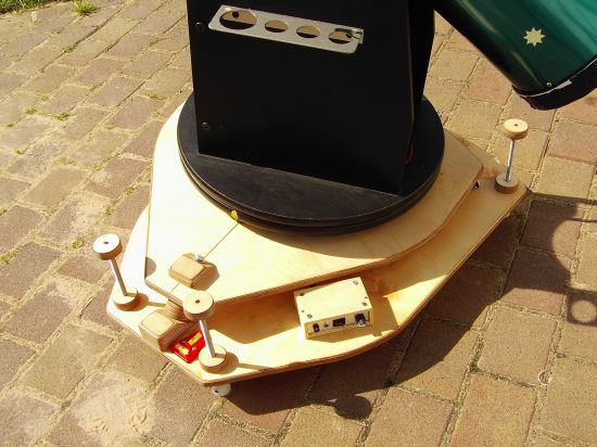
In order to improve the prototype I constructed the final version of my EQ platform. I implemented following features:
Dimensions were calculated using the same Excel-Workbook as used for the prototype. The workbook now includes a parts list and prices as well.
|
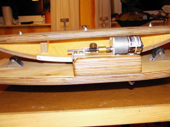
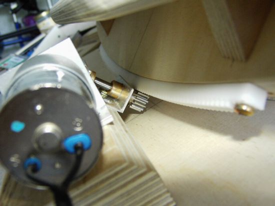
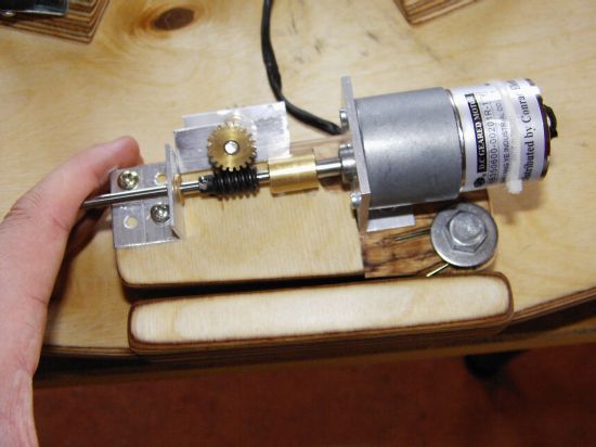
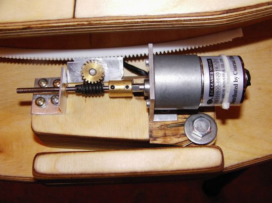
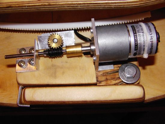
No friction driveThe main problem with the prototype is the friction drive slipping under low temperature conditions. Reiner Vogel solved this problem by using a vertical mounted segment in stead of an angled segment. Unfortunately, this would require elliptical segments so I prefered to keep the angled circular segment instead because it is easier to build. In order to avoid slipping, I used a rack and a spur gear on the segment:
This approach turned out to have two additional advantages: 1. Rack and spur gear have an higher reduction ratio than the former friction drive so the motor runs almost noiseless at much lower speed. 2. The full 25 cm rack length allows a tracking time which is about twice as long as the prototype's tracking time. The platform runs 110 minutes before it needs to be reset to its starting position. |
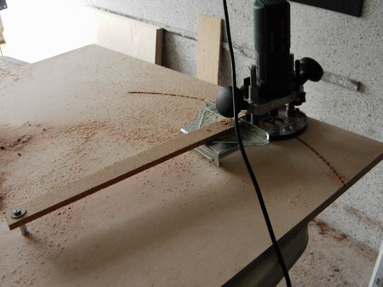
low costCompared to commercially offered EQ platforms the design is rather cheap to realise. Material costs amount to something like 160 Euros. Easy to buildThe most difficult part probably is the segment. The following pictures show how it can be build using regular home worker tools. With the addition of a centering pin the side fence of a power router can be converted into an adjustable trammel bar for rotating the machine about a central point. The radius corresponds to value C in the Excel workbook:
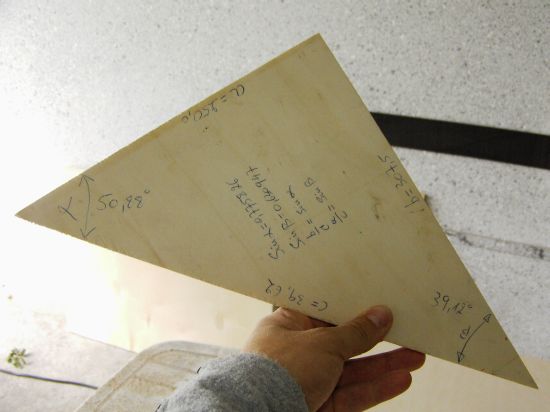
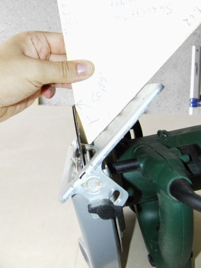
I constantly needed two angles: alpha (lattitude of the desired observing spot) and beta (90 degrees minus alpha). So I first made a template:
Using the template to adjust the circular saw:
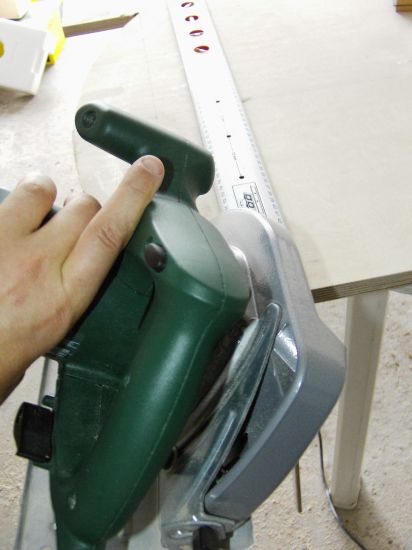
Using a clammed aluminium ruler as a guide batten the segment is cut under the desired angle (beta):
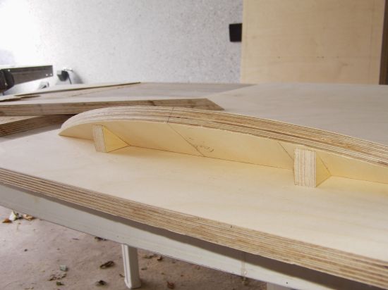
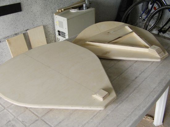
Using the same template two small triangular pieces of multi-plywood are cut. These will support the angled segment:
Both platform and ground boards are reinforced with stripes of 18mm plywood. All joints were made using wooden dowels and wood-glue. In contrast to screws dowels are not magnetic and don't disturb the compass during platform setup:
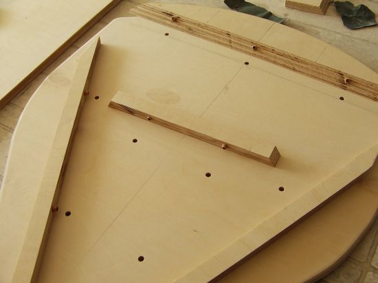
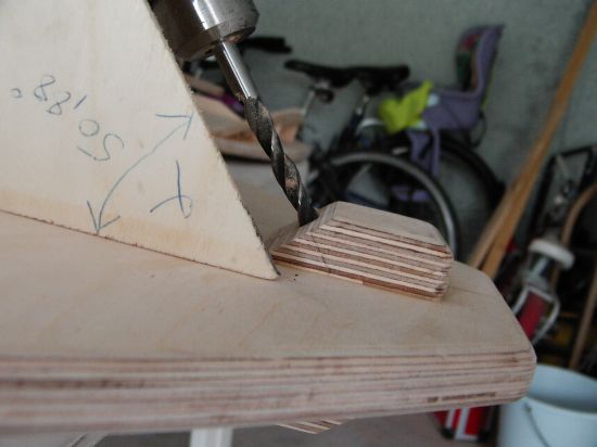
The next obstacle is the borehole for the southern bearing. Once again, the template serves well:
At the end the edges of all boards were rounded with the router and an edge-forming cutter. The first wood finish was linseed oil, a second finish teak oil left a nice looking workpiece. The next picture shows the southern bearing. By the way, the wooden rings were made using a two inch hole saw.
|
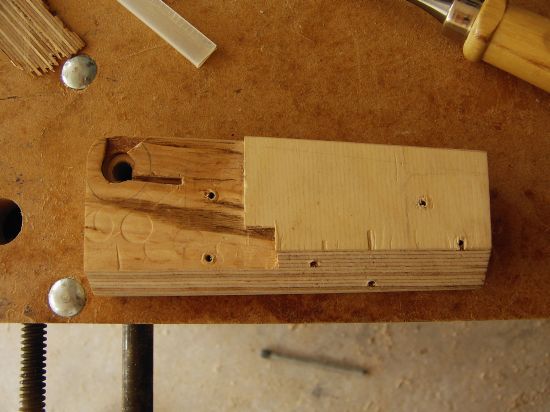
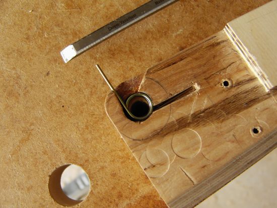
easy Platform resetAfter 110 minutes tracking the platform needs to be set back to the initial point. This action requires the spur gear to be detached from the rack. I realised this by countersinking two springs in the motor block:
The upper (right-hand) spring...
... and the lower (left-hand) spring. Note that I added an Ebony-Star-like layer which allows the block to slide smoothly on the ground board.
In order to reset the platform the motor block can be drawn back with one hand and the platform is moved back with the other hand. Even with an heavy telescope on the platform this action is a child's play!
During star tracking the springs move the spur gear towards the rack. It is important that the segment is mounted in such a way that the rack moves closer to the motor block during star tracking. In that way the platform presses against the spring force ensuring full contact between spur gear and rack. That is why I had to mount the segment slightly out of the right angle. (About 1 mm)
This hook keeps the motor unattached during transport:
|
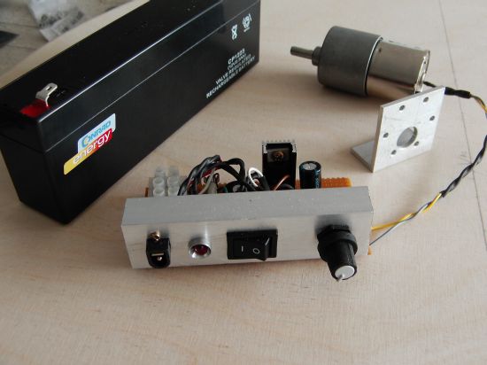
electronic speed controlA simple electronic circuit (Thanks Ekkehard !) based on the LM317 voltage regulator was used. If you don't want to solder, assembled printed circuit boards are commercially available. I build my own version on breadboard: 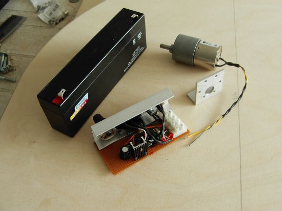
The lead-acid battery can be charged using the 12V connector:
|
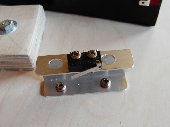
Automatic power offThe motor needs to be stopped when the spur gear reaches the end of the rack. A well positioned microswitch cuts off the 12V power at the right moment:
|
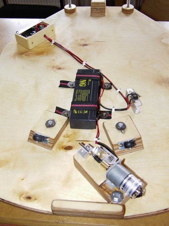
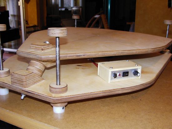
No strumble traps (cables)This is how the electronic assembly looks like. No wires are left lying about the observing place at night because the battery is mounted on the ground board along with the speed control unit and all the necessary cabling. I positioned the speed control unit at the left hand, this is where I mostly sit when observing southeastern - southern or southwestern skies.
|
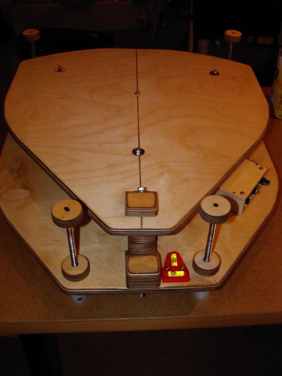
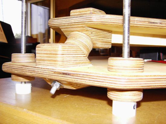
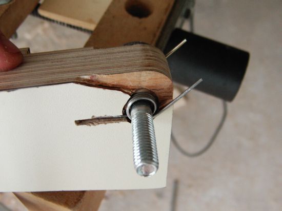
adjustable feetTeflon feet are mounted on a high-grade steel threaded M10 rod. Both wooden rings in the middle carry M10 nuts. The lower ring is fixed to the ground board, the ring in the middle is not fixed and serves as a lock nut allowing to fix the feet securily at any desired position. The upper ring is just a knob.
|
Transport lock and carry handle
|
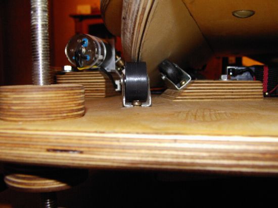
high accuracy and stabilityAlthough this platform was designed with the visual observer in mind, accuracy even allows short exposure or webcam photography. A 400 times magnificated Jupiter stays more than 40 minutes in the eyepiece which is entirely satisfactory for visual observation. There was a stability issue though... The initial construction turned out to be a bit unsteady and susceptible to wind. Two additional wheels solved the problem:
These wheels run on the back edge of the segment and need a running surface. I patiently grinded the edge to make sure that both wheels support the platform board at any telescope position. It sounds difficult, but the job was done in about 30 minutes. Here is how it looks like:
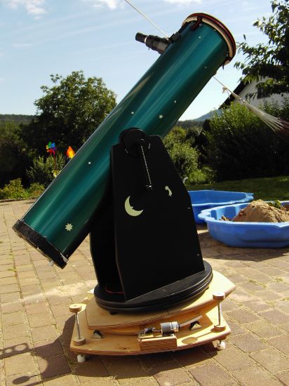
I grant that 18 mm birch multi-plywood is heavy but the platform is very stable and I am pretty sure that it can cope with heavier equipment such as 12 inch dobsonian telescopes...
|