Sketching astronomical objects
This site is dedicated to my astronomical drawings.
Sketching deep-sky objects helps to improve observing skills.
Over time - my technique should become better...
- You are here:
-
Home

-
English (en-GB)
-
Self made
- Self made - Articles
Self made
Star maps
Self made - Articles
Tuesday, August 14, 2007
|
Astronomical sketching is much easier if your telescope "follows" the objects in the sky. Star tracking is generally not available on dobsonian telecopes unless the telescope is placed on a so called equatorial platform. An EQ platform basically is a low rotating table carrying a telescope. The working principle is very well documented on the home pages of Jan Van Gastel (English) and Reiner Vogel (German).
|
Wednesday, Januar 17, 2007
|
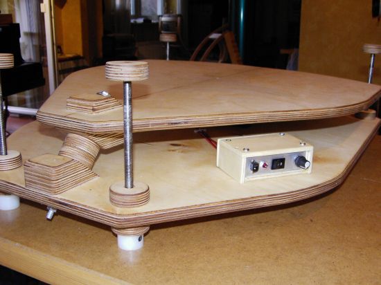
In order to improve the prototype I constructed the final version of my EQ platform. I implemented following features:
Dimensions were calculated using the same Excel-Workbook as used for the prototype. The workbook now includes a parts list and prices as well.
|
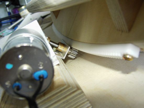
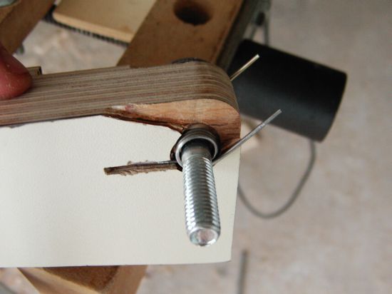
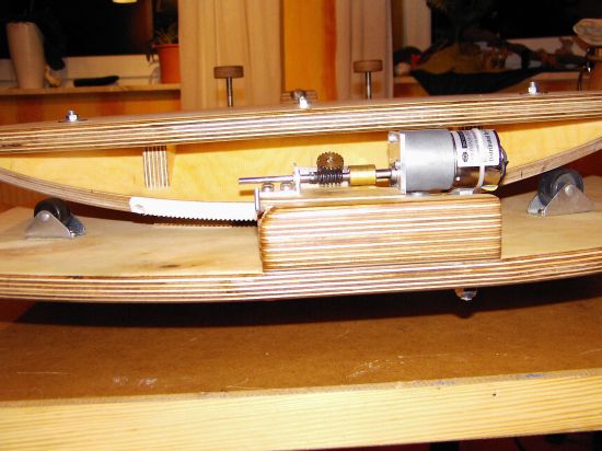
No friction driveThe main problem with the prototype is the friction drive slipping under low temperature conditions. Reiner Vogel solved this problem by using a vertical mounted segment in stead of an angled segment. Unfortunately, this would require elliptical segments so I prefered to keep the angled circular segment instead because it is easier to build. In order to avoid slipping, I used a rack and a spur gear on the segment:
This approach turned out to have two additional advantages: 1. Rack and spur gear have an higher reduction ratio than the former friction drive so the motor runs almost noiseless at much lower speed. 2. The full 25 cm rack length allows a tracking time which is about twice as long as the prototype's tracking time. The platform runs 110 minutes before it needs to be reset to its starting position. |
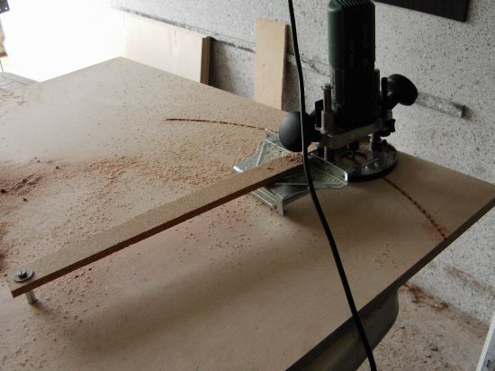
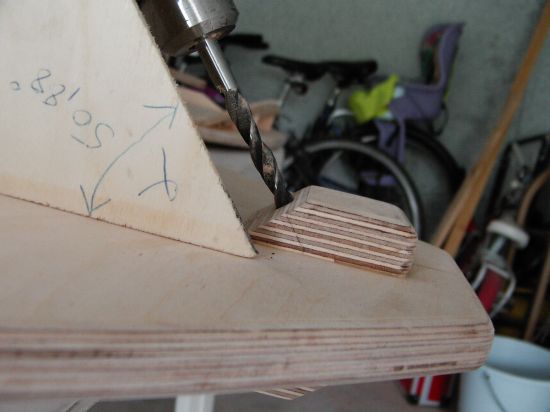
low costCompared to commercially offered EQ platforms the design is rather cheap to realise. Material costs amount to something like 160 Euros. Easy to buildThe most difficult part probably is the segment. The following pictures show how it can be build using regular home worker tools. With the addition of a centering pin the side fence of a power router can be converted into an adjustable trammel bar for rotating the machine about a central point. The radius corresponds to value C in the Excel workbook:
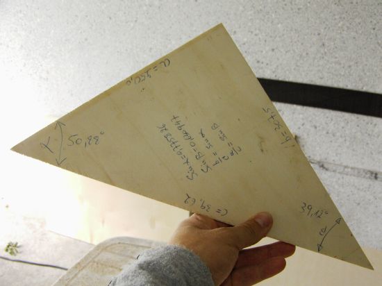
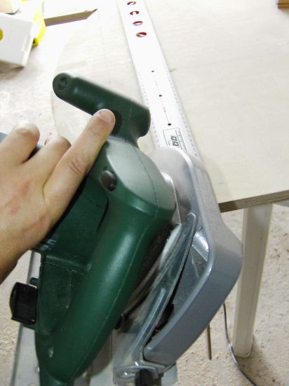
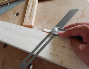
I constantly needed two angles: alpha (lattitude of the desired observing spot) and beta (90 degrees minus alpha). So I first made a template:
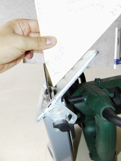
Using the template to adjust the circular saw:
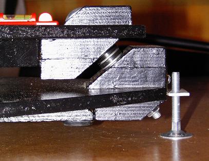
Using a clammed aluminium ruler as a guide batten the segment is cut under the desired angle (beta):
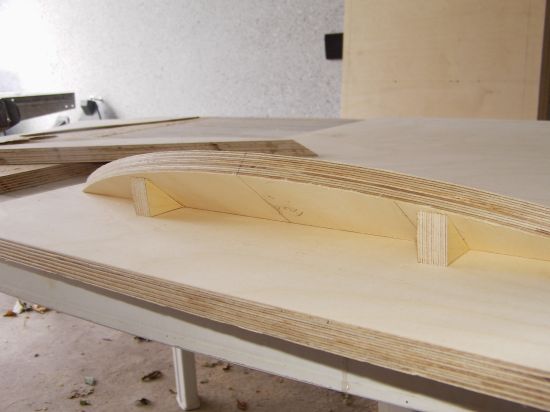
Using the same template two small triangular pieces of multi-plywood are cut. These will support the angled segment:
Both platform and ground boards are reinforced with stripes of 18mm plywood. All joints were made using wooden dowels and wood-glue. In contrast to screws dowels are not magnetic and don't disturb the compass during platform setup:
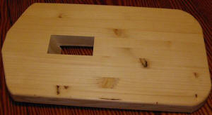
The next obstacle is the borehole for the southern bearing. Once again, the template serves well:
At the end the edges of all boards were rounded with the router and an edge-forming cutter. The first wood finish was linseed oil, a second finish teak oil left a nice looking workpiece. The next picture shows the southern bearing. By the way, the wooden rings were made using a two inch hole saw.
|
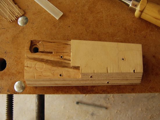
easy Platform resetAfter 110 minutes tracking the platform needs to be set back to the initial point. This action requires the spur gear to be detached from the rack. I realised this by countersinking two springs in the motor block:
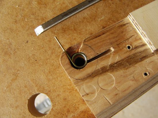
The upper (right-hand) spring...
... and the lower (left-hand) spring. Note that I added an Ebony-Star-like layer which allows the block to slide smoothly on the ground board.
In order to reset the platform the motor block can be drawn back with one hand and the platform is moved back with the other hand. Even with an heavy telescope on the platform this action is a child's play!
During star tracking the springs move the spur gear towards the rack. It is important that the segment is mounted in such a way that the rack moves closer to the motor block during star tracking. In that way the platform presses against the spring force ensuring full contact between spur gear and rack. That is why I had to mount the segment slightly out of the right angle. (About 1 mm)
This hook keeps the motor unattached during transport:
|
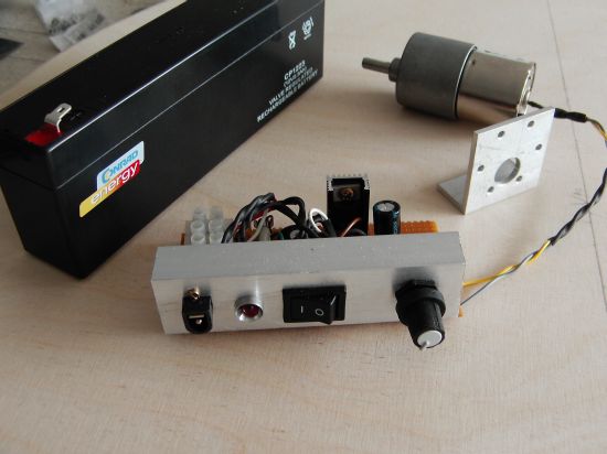
electronic speed controlA simple electronic circuit (Thanks Ekkehard !) based on the LM317 voltage regulator was used. If you don't want to solder, assembled printed circuit boards are commercially available. I build my own version on breadboard: 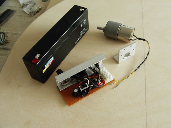
The lead-acid battery can be charged using the 12V connector:
|
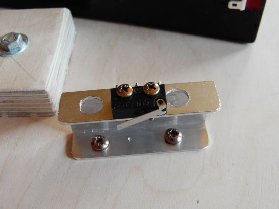
Automatic power offThe motor needs to be stopped when the spur gear reaches the end of the rack. A well positioned microswitch cuts off the 12V power at the right moment:
|
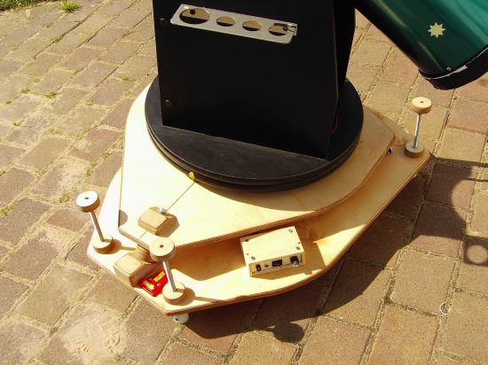
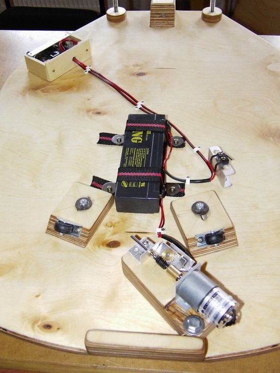
No strumble traps (cables)This is how the electronic assembly looks like. No wires are left lying about the observing place at night because the battery is mounted on the ground board along with the speed control unit and all the necessary cabling. I positioned the speed control unit at the left hand, this is where I mostly sit when observing southeastern - southern or southwestern skies.
|
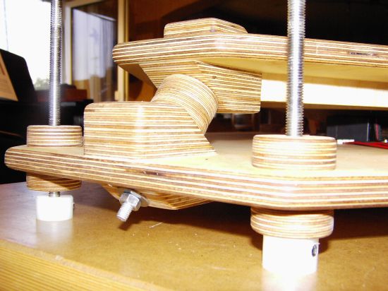
adjustable feetTeflon feet are mounted on a high-grade steel threaded M10 rod. Both wooden rings in the middle carry M10 nuts. The lower ring is fixed to the ground board, the ring in the middle is not fixed and serves as a lock nut allowing to fix the feet securily at any desired position. The upper ring is just a knob.
|
Transport lock and carry handle
|
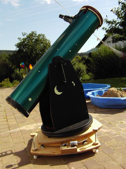
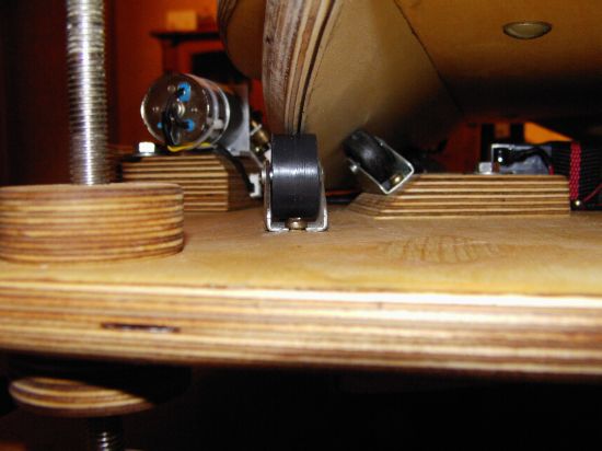
high accuracy and stabilityAlthough this platform was designed with the visual observer in mind, accuracy even allows short exposure or webcam photography. A 400 times magnificated Jupiter stays more than 40 minutes in the eyepiece which is entirely satisfactory for visual observation. There was a stability issue though... The initial construction turned out to be a bit unsteady and susceptible to wind. Two additional wheels solved the problem:
These wheels run on the back edge of the segment and need a running surface. I patiently grinded the edge to make sure that both wheels support the platform board at any telescope position. It sounds difficult, but the job was done in about 30 minutes. Here is how it looks like:
I grant that 18 mm birch multi-plywood is heavy but the platform is very stable and I am pretty sure that it can cope with heavier equipment such as 12 inch dobsonian telescopes...
|
Saturday, July 01, 2006
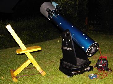
A simple cost effective way to build stable furniture without the need of specialized wood worker's skills.Cheap and Stable
This chair costs less than 15 Euros. The seated position is adjustable in a range from 30 cm until 80 cmand it can be build using regular home worker tools. A jigsaw and a router can be handy but are not really necessary. The use of a power sander or a portable planer can speed up things enormously. |
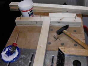
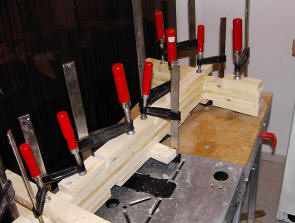
The roof batten systemThe cheapest wood available is the so called roof batten which is a blunt plank of common spruce typically 2,5 x 4 x 200 cm. I just layered multiple battens in order to build an amazingly strong construction. The first layer of planks is layed out on the table, wood-glue is applied and the second layer is nailed on top of the first layer. The same procedure is used for the third layer:
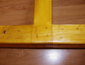
All surfaces are smoothed using router and power sander. Note the filled nail holes of the last layer:
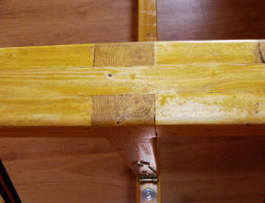
This T-joint looks nice and is very strong:
The seatI used the same layered batten system. The seat counts 10 layers. Each batten is positioned in a way that the direction of the growth rings alternate, doing so will avoid distortion caused by shrinkage movement.
Layer 5 and layer 6 consist of 2 battens each. The smallest are cut under an angle, all other are rougly planed down to about 3 cm thickness using a power planer:
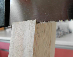
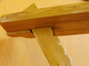
The teethI copied the angle for the teeth from my child's chair, that angle measures about 20 degrees. I wanted one teeth per 4 cm resulting in 15 levels. It turned out that I don't really need 15 levels during observation, 10 levels would have been okay.
Of course, I could have used any saw but I used a Japanese hand saw to cut the teeth. Japanese saws cut on the pull stroke, so the blades are much thinner. As a result, they cut a narrow kerf with no tearing of the grain. Unfortunately, Japanese saws are expensive.
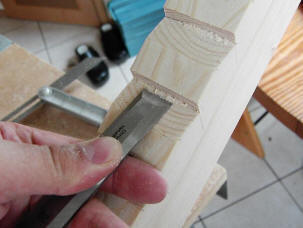
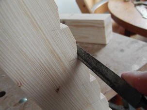
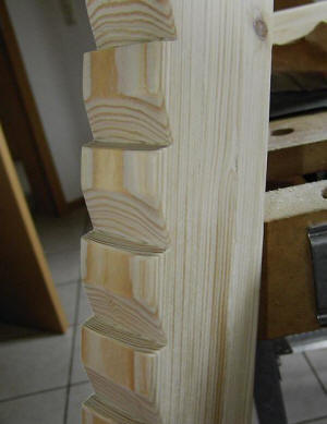
Finishing the teeth:
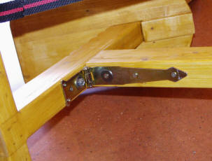
The assemblyAn hinge keeps the whole thing together. An M8 carriage bold keeps the hinge in place. The chair is foldable and fits on the back seat of my car.
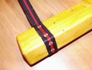
An additional belt between the feet prevents the hinge from being destroyed by overload:
At the end, varnish was applied:
|

Tuesday, January 10, 2006
|
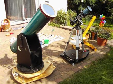
I decided to build a prototype first and searched the internet for information. Google provided tons of useful web links. I selected the platform design of Reiner Vogel (German) because of its brilliant and simple design.
I needed to recalculate the original design for my telescope because of the different centre of gravity. I spend two weekends calculating the whole thing... 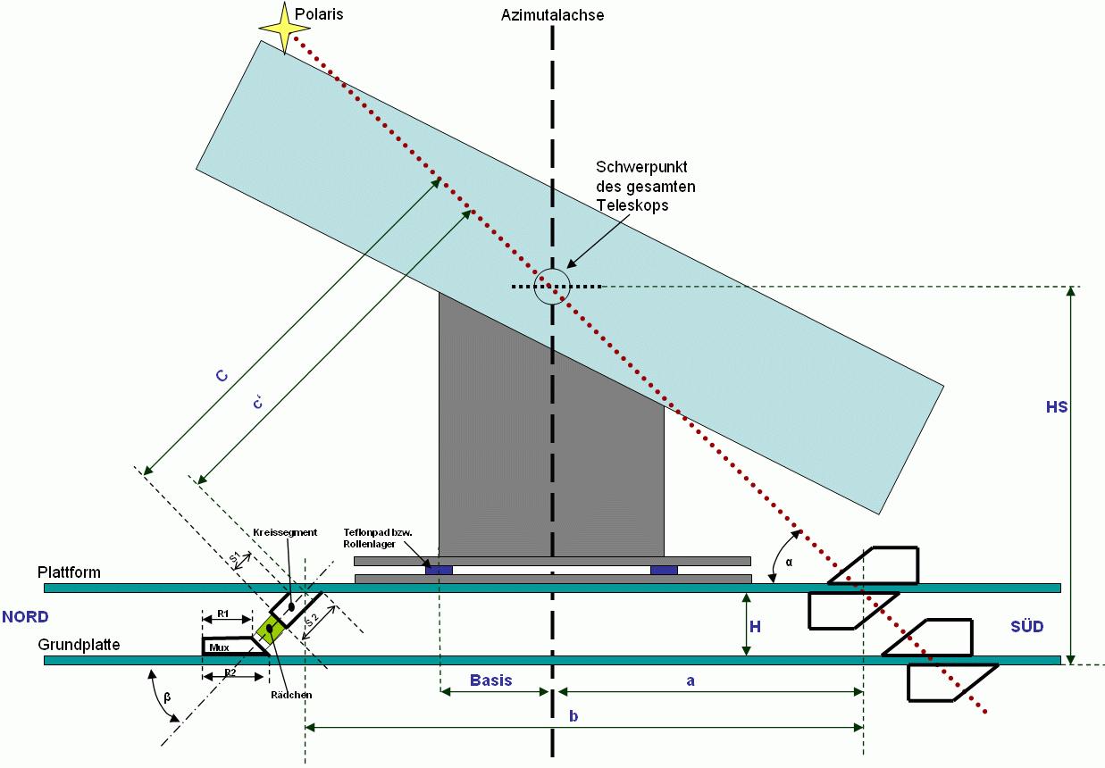
All necessary calculations were done using an Excel-Workbook which can be used to recalculate all dimensions for any telescope. Just enter your telescope's data in the Excel-Workbook. Thanks to the homepages of Jan Van Gastel (English) and Reiner Vogel (German), understanding and building this platform was not too hard. I am using it since January 2006 and I can't imagine observing without it! |
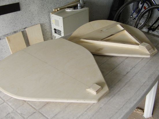
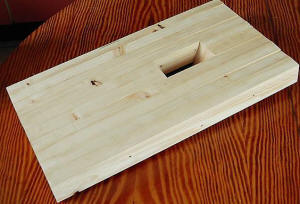
The different partsThe ground board:
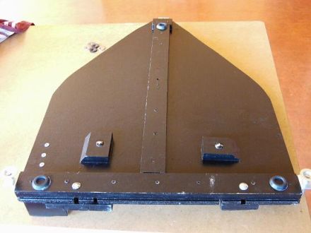
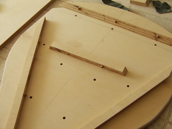
The bottom side of the ground board. It was necessary to strengthen the board with stripes of 18mm plywood.
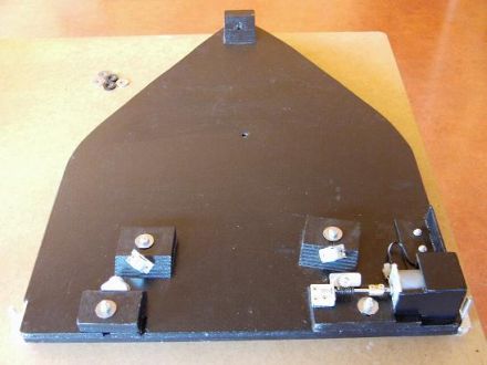
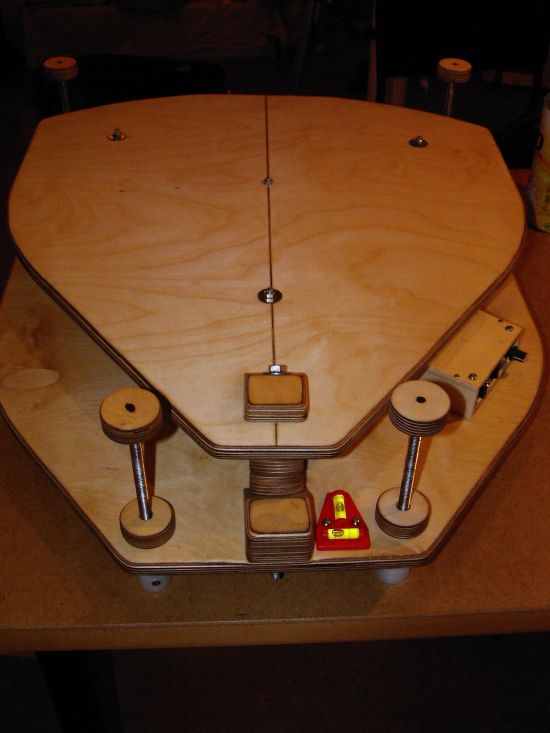
The upper platform board. The small spirit level helps to set up the platform. The three screws are just marks for the feet of the telescope.
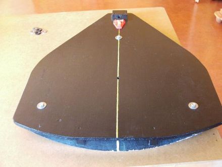
The bottom side of the platform board. Once again, I used stripes of plywood to strengthen the board. The magnetic screws disturb the compass during platform setup, so I painted a yellow North - South line on the board which helps to align the platform while holding a compass at a save distance.
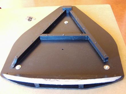
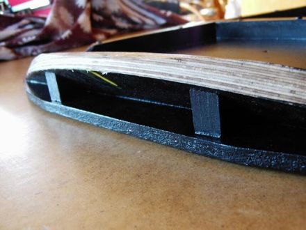
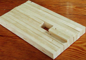
The platform board (side view). The segment was made using a power router and a home-made circular guide. This segment allows almost 60 minutes star tracking.
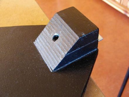
The southern bearing is a block of glued multi-plywood. The angle corresponds to the geographical lattitude of the observation spot, which is in my case 50.8 degrees.
One single screw holds both parts together. The bearing runs on plastic and steel washers.
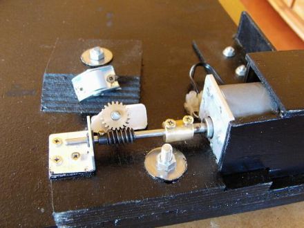
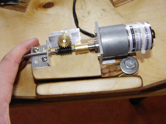
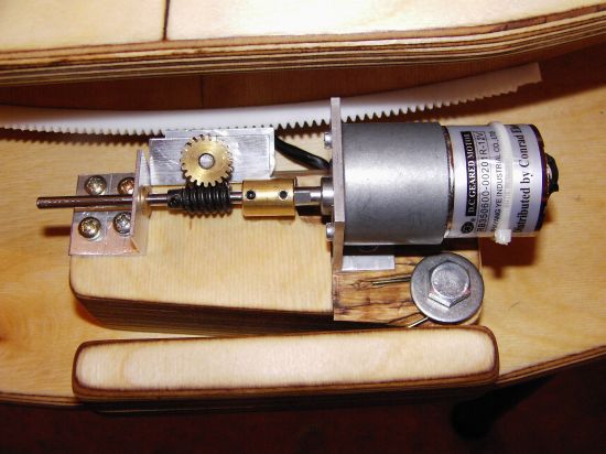
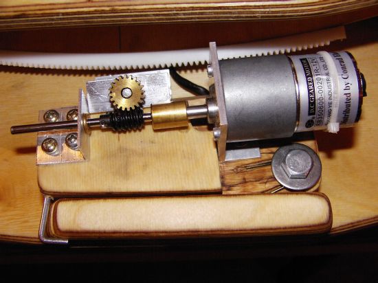
The motor is a geared DC motor with a reduction ratio of 1:600. The worm wheel set has a reduction ratio of 1:20. The shaft directly drives the wooden segment.
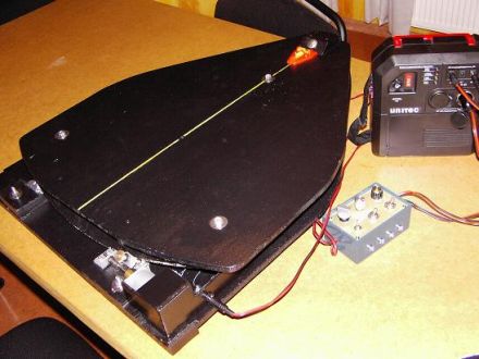
Initially I simply used a 50 ohm power potentiometer to regulate the motor speed. Later, I used an electronic circuit with an LM317 voltage regulator and a 12V power supply. that's it....Here is a picture of my telescope on the platform. The accuracy is sufficient enough to keep a planet more than 30 minutes in the eyepiece. The cables turned out to be stumble traps at night. Also, the friction drive slipped during winter because of the shaft being iced. So I solved these problems and constructed the final version.
|